How to Build a Raspberry Pi Based Sensorgnome
Introduction
SensorGnomes are an essential component of the Motus Wildlife Tracking System. These devices act as radio receivers in a world-wide network, listening to radio transmitters that have been deployed on birds, bats, and insects by researchers trying to answer questions about movements on multiple scales.
The SensorGnome was originally designed at the Phil Taylor Lab at Acadia University and is now available for sale by Compudata and RFS Scientific.
Here I explain how to build one of these devices yourself.
See Sensorgnome.org for more information.
Building a Sensorgnome
Supplies
Raspberry Pi Model B v1.2
Raspberry Pi Case
GPS HAT
40-pin header
CR 1220 battery
uFL to SMA Adaptor
GPS Antenna
Micro SD Card and Reader - minimum of 16 GB recommended
Laptop
USB Power Adaptor with Micro USB
Waterproof Momentary Pushbutton Switch with LED
Socket for Pushbutton
Ethernet Cable (optional)
Tools
Soldering iron
Solder
Flux
Solder wick and/or solder sucker to clean up any mistakes
Hot glue gun + hot glue
Step 1: Solder 40-pin Header to GPS HAT
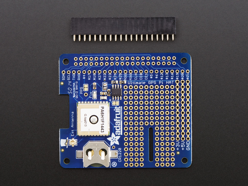
GPS HAT purchased from Adafruit typically comes with a 40-pin header that must be soldered to the board.
Instructions on soldering will not be described here.
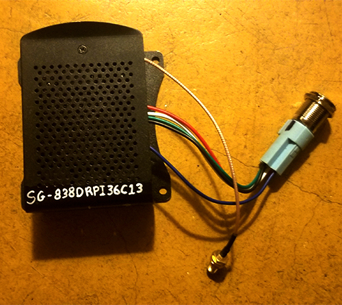
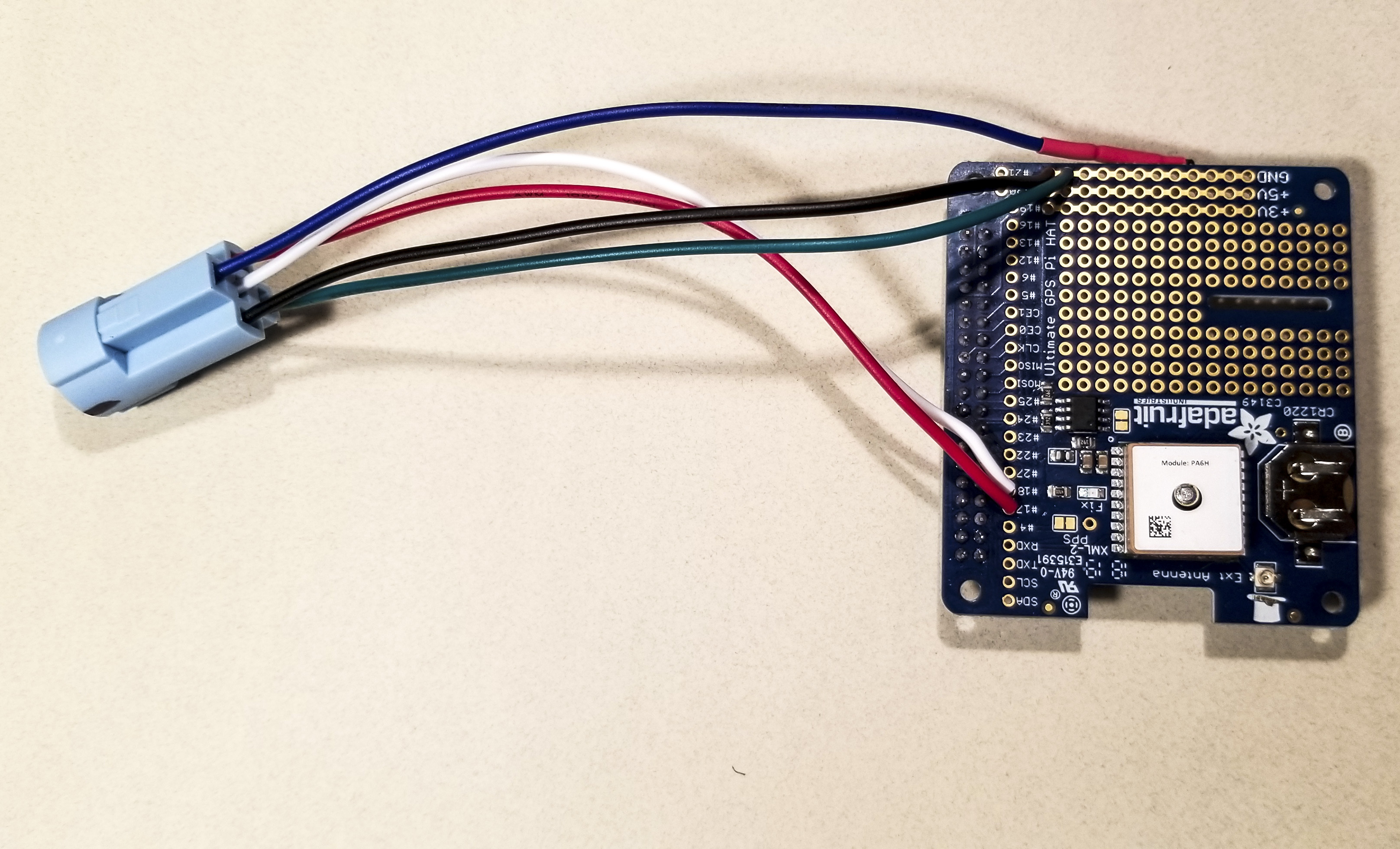
Step 2: Soldering Pushbutton to GPS HAT
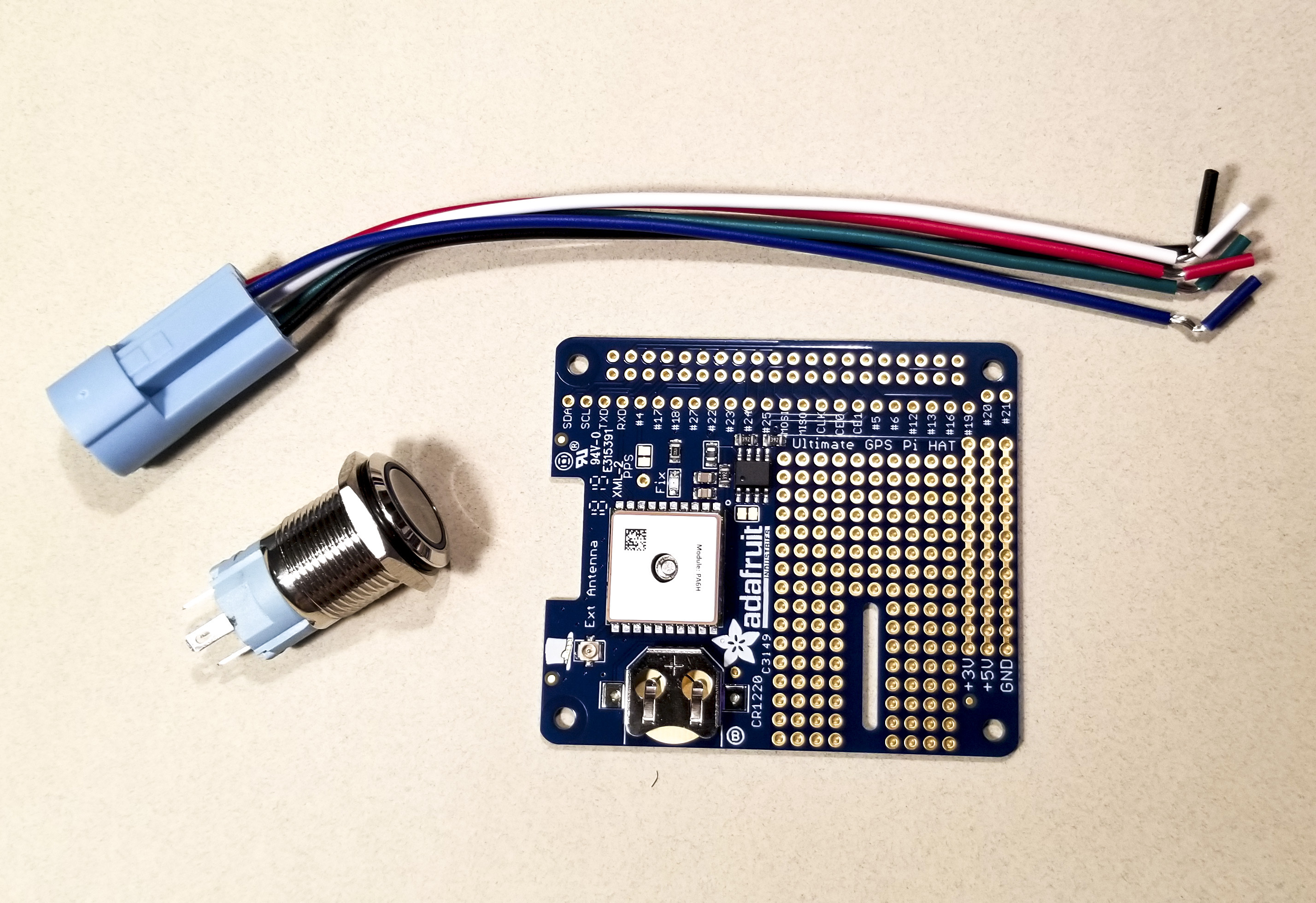
Pushbutton comes with multiple pins – see the specifications for your button to identify each terminal. Plug the pushbutton socket into the pushbutton so you know which wire corresponds with each pin.
Pins are soldered to the GPS HAT in the following order:
Netagive and common switch terminals to ground
Positive to GPIO#17
Normally Open to GPIO#18
Solder the wires of the Pushbutton Socket through the topside of the boards so that the wires come out of the topside.
Double-check you are soldering the wires to the board in the correct order before you start soldering. There may be one wire left unused - you can leave it loose.
Instructions on how to solder will not be outlined here.
Button Symbol |
Button Terminal |
GPS HAT |
|---|---|---|
- |
Negative |
Ground |
C1 |
Common Switch |
Ground |
+ |
Positive |
GPIO#17 |
NO1 |
Normally Open |
GPIO#18 |
Step 3: Assembling GPS HAT
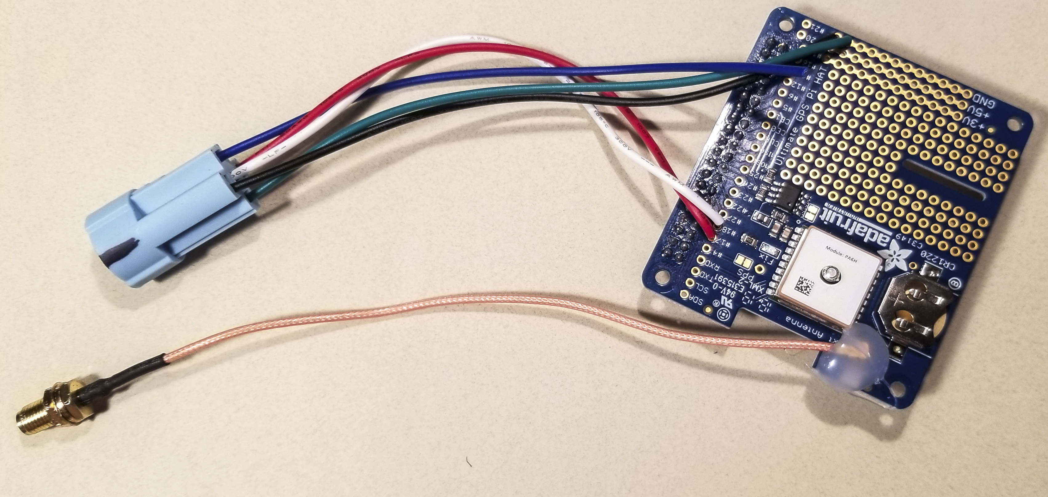
Plug the uFL end of the uFL-to-SMA connector onto the uFL port on the GPS HAT, located adjacent to the square GPS Module and battery slot.
Use a hot glue gun to help fix the uFL connector to the board.
Insert the CR1220 battery into the battery slot, positive (flat) side up.
Step 4: Assembling Raspberry Pi
Plug the GPS HAT on to the Raspberry Pi board using the 40-pin header.
Install the Raspberry Pi + GPS HAT in the Raspberry Pi Case.
Step 5: Install Software on Raspberry Pi
Insert the MicroSD card in to the MicroSD card adaptor.
Plug the MicroSD card adaptor into your laptop.
Format the MicroSD card as VFAT or FAT32 file system.
Unzip the contents of the software package onto the MicroSD card.
Safely remove the MicroSD card from your laptop.
Insert the MicroSD card into the SD card slot of your Raspberry Pi.
Plug in your USB Power Adaptor into an AC wall outlet and then into the Raspberry Pi to power on your device.
You should see the LED on the Raspberry Pi.
Allow 1-2 minutes for the Raspberry Pi to boot up.
Once it has booted the Pushbutton should begin blinking if you press it once. Press it once again to make it stop blinking.
Step 6: Connect to Your Raspberry Pi (Wi-Fi)
Once the Raspberry Pi has booted up, double-press the Pushbutton switch to activate the Wi-Fi.
Once active, the Pushbutton should blink slowly at a rate of 0.5 seconds on and 0.5 seconds off.
Using a phone or laptop, look for a Wi-Fi network with a name such as “SG-###RPI3###”, where ‘#’ can be any letter or number.
Connect to the network using the same name of network as the password.
Once connected, open your web browser and navigate to the following address: 192.168.7.2
You should see a web page that says ‘I am your SensorGnome’ with a bunch of live information about the device. A full description of the webpage will be described later. For now, the fact this page is loading will inform you that the Sensorgnome software has correctly been installed and that you have successfully connected to it.
Step 7: Connect to Your Raspberry Pi (Ethernet)
This is an alternative method to connecting to your SensorGnome from the method above.
Once the Raspberry Pi has booted up, insert the Ethernet Cable. cable into the Raspberry Pi’s Ethernet port and your laptop.
Once connected, open your web browser and navigate to the following address: sgpi.local
You should see a web page that says ‘I am your SensorGnome’ with a bunch of live information about the device.
If you are having trouble connecting, try the previous step with Wi-Fi.
Step 8: Access Your SensorGnome’s Internal Folders
While connected to your Raspberry Pi via Wi-Fi or Ethernet, you can:
Download receiver data.
Set Wi-Fi network properties (for automated data download and remote diagnostics)
Add or change information such as deployment name and contact information.
Change the receiver listening frequency and GPS logging rate.
Add or change the on-board tag database.
Accessing the internal storage requires software known as an ‘FTP’ client. FTP is a file transfer protocol which basically provides access to another computers storage system via a wired or wireless connection. At this time we recommend collaborators use the client ‘FileZilla’ which is a safe, open-source software available on Windows, Mac, and Linux operating systems. There is also FTP clients available for smartphones; on Android you can use the app ‘ES File Explorer’ available on Google Play; for Apple and Windows there is no known software at this time.
The following steps outline how to access the internal folders of your SensorGnome using FileZilla:
Download FileZilla from their website:
Install the program with its default settings
Open the program and in the top bar you will see four text fields labelled Host, Username, Password, and Port.
In the ‘Host’ field, enter the address “sftp://192.168.7.2” if you are connected via Wi-Fi. If you are connected by an Ethernet cable, enter the address “sftp://sgpi.local”
For the username enter “root” and for the password enter “root” as well. The port field should be left blank.
Click the ‘Quickconnect’ button and you should see the following progress text in the Status frame.
The folders visible on the left-hand side of the window are on your laptop (‘Local Site’) – we will call this sections frame 1. After clicking the ‘Quickconnect’ button, you should also see folders appear in two frames located on the right-hand side of the window – this is the internal storage of your SensorGnome (‘Remote Site’). We will call the top and bottom sections frame 2 and frame 3, respectively.
To navigate through your SensorGnome’s storage, you can use either of frames 2 or 3 but note only frame 3 shows files (frame 2 is for navigation only!).
Navigate to the ‘root’ of the Sensorgnome, either by clicking on the folder ‘/’ in frame 2 or by clicking the ‘..’ folder in frame 3 until you can no longer navigate further.
To access data stored on the SensorGnome, navigate through the following folders: “media” / “internal_SD_card” / “SGdata”. In the final folder you will see one folder for each day the SensorGnome has been collecting data. Folders will be labelled with the following date format “YYYY-MM-DD”.
To copy files from the SensorGnome to your laptop, simply select all the folders you wish to download, right click and select ‘download’. They will be automatically copied to the folder you have open in frame 1.
See the following steps to make changes to the SensorGnome.
Step 9: Set Wi-Fi Network Properties
You can use the SensorGnome’s on-board Wi-Fi to make the device connect to our web servers and automatically download data so you don’t have to do it manually. In addition, you can use the interface available on sensorgnome.org to view the SensorGnome’s live web interface and diagnose any issues it may have. At this time, this feature is only compatible with Wi-Fi networks that are WPA2 password protected; networks without a password will not work! Alternatively, you can use a hard-wired connection by plugging an Ethernet cable into your SensorGnome and router. To use Wi-Fi, follow these steps:
From the root folder, navigate to the following folder:
boot/uboot.In here you can find a file called ‘network.txt’. Right click on it and select ‘view/edit’.
This file contains all the instructions required to set the Wi-Fi. Once completed, save and close the file.
To make the changes come into effect, you will need to reboot your SensorGnome.
Once rebooted, review that your SensorGnome has been connected successfully by searching for its serial number in the list of receivers found on http://sensorgnome.org/status.
Step 10: Add or Change On-board Tag Database
It is not required to add a tag database to your SensorGnome in order to get detections of your tags. But note, tags must always be registered on Motus.org prior to deployment, otherwise you will never get detections! Tag databases are only required if you wish to identify the specific tags while viewing your SensorGnome’s live web interface. This can be useful when testing tags or your SensorGnome in the field, or when using the SensorGnome to aid in tag activation, rather than using a Lotek receiver. To install a tag database on your SensorGnome, follow these steps:
Go to Motus.org and navigate to ‘Manage Tags’ on the project of choice.
Click the ‘Download Tag Database’ button on the top-right corner of the page.
Select the and download database you wish to add (they are labelled by registration date).
Rename the file to ‘SG_tag_database’ – keep the ‘.sqlite’ file extension.
While connected to the SensorGnome with FileZilla, navigate to the ‘root’ folder and then go to ‘boot’ / ‘uboot’.
Copy the tag database to this folder – if a file already exists, rename it to something else or delete it.
Restart your SensorGnome to load the new tag database.
Use either steps 6 or 7 to connect to your SensorGnome and view the web interface.
If your database was installed correctly, you should see the tags listed in the text box located on the bottom of the page. If not, you may need to try again.